Multi‑cavity molds present unique challenges for temperature sensing because each cavity must produce identical parts, and any temperature variation between cavities leads to dimensional mismatch, weight variation, and aesthetic defects. In an ideal arrangement, each nozzle or each hot drop should have its own dedicated thermocouple and independent temperature control zone. This allows individual adjustment to compensate for unequal heat loss due to different distances from the manifold, cooling lines, or gate geometry. However, for very high cavity counts (e.g., 64 or 96 cavities), it may be cost‑prohibitive to instrument every nozzle. In such cases, a strategic sampling approach is used: thermocouples are placed on cavities located at the center, edge, and corners of the layout, where thermal conditions are most extreme. The manifold itself often has multiple thermocouples along its length to ensure uniform heating. In a typical hot runner manifold, thermocouples are embedded at key branch points to monitor the temperature distribution from the sprue to each drop. The goal is to maintain all zones within ±1°C of the setpoint, but in practice, the outermost cavities tend to run cooler due to heat loss to the mold frame. To counteract this, heaters are often zoned with higher power density at the edges, and the thermocouples must be positioned to reflect these gradients accurately. Another important consideration is the location of the thermocouple relative to the gate. For valve‑gated systems, the thermocouple should be placed close to the valve pin bushing to capture the temperature that affects gate opening and closing behavior. For open‑gate nozzles, the sensor should be near the tip to monitor melt temperature just before injection. In multi‑cavity molds, it is also common to use a "master" thermocouple as the control sensor for a group, while others are used for monitoring only, triggering alarms if they deviate significantly. However, advanced controllers now offer individual zone control even with shared thermocouple sensing, using thermal modeling to estimate unmeasured zones. When arranging thermocouples, ensure that wiring harnesses are organized and labeled clearly, as mis‑connections are a common source of troubleshooting nightmares. Cable lengths should be equalized to avoid differing signal attenuation. Also, consider the ease of maintenance – thermocouples in deep cavities may require longer probes or right‑angle connectors to facilitate removal. Overall, a well‑planned thermocouple arrangement in a multi‑cavity mold not only improves part consistency but also reduces cycle time by allowing tighter temperature control without overshooting.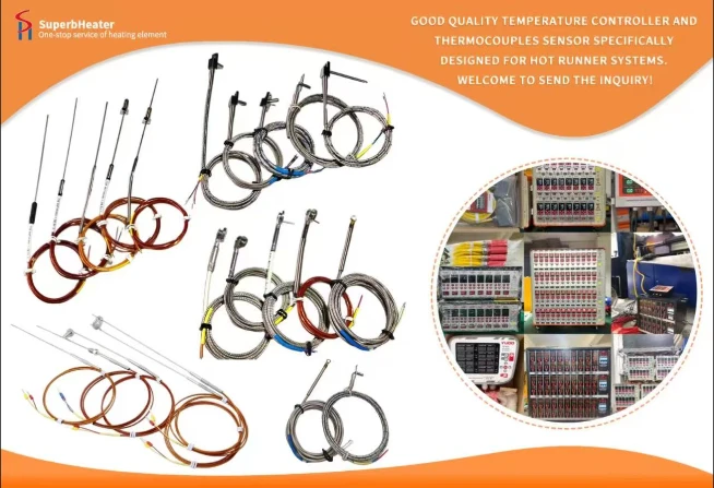

 English
- English
- Français
- Deutsch
- 日本語
- Italiano
- Español
- Português
- русский
- Indonesia
- عربي
- Ελληνικά
- Polski
- فارسی
- עברית
- Kreyòl Ayisyen
- 한국어
- Türkçe
- slovenčina
- Bai Miaowen
- Cymraeg
- dansk
- Lietuvių
- Malti
- Svenska
- Srbija jezik (latinica)
- O'zbek
- ไทย
- suomi
- magyar
- Eesti
- Català
- slovenščina
- Melayu
- Български
- اردو
- România limbi
- bosanski
- हिंदी
- Gaeilgenah Éireann
- Việt Nam
- বাংলা
- íslenska
- Norsk
- Latviešu
- hrvatski
- Nederlands
- Čeština
- українська


