I. Optimisation of Runner Structure at the Root Cause
Ensure that the length, diameter, and bending angle of the runners from the main runner to each cavity are entirely consistent, thereby eliminating differences in melt delivery resistance, by prioritising H-type and X-type radial symmetrical runner layouts.
Finely polish the inner walls of all runners and employ circular or trapezoidal runner cross-sections to mitigate melt flow friction resistance and dead zones for material accumulation.
Add flow-blocking steps to the runners at the front of cavities with excessively rapid feed rates for asymmetrical layout moulds that are already in production and cannot be modified. Additionally, widen the runners in cavities with slow feed rates as necessary. Adjust the feed rate of each cavity manually.
II. Centralised Management of Venting and Gating Systems
Guarantee that the gates in all cavities are identical in terms of their size, position, depth, and width. Ensure that the melt's instantaneous flow rate upon entry is consistent by strictly prohibiting situations in which certain cavities have large gates and others have small gates.
Symmetrically placed venting channels with uniform depth and location are prioritised at the end of the melt flow to prevent trapped air in individual cavities from obstructing melt flow and causing filling delays. Each cavity is equipped with these channels.
III. Control of the Injection Moulding Process with Precision
A stable and uniform molten state of the raw material is guarantyd by a uniform barrel temperature, which prevents localised high temperatures that result in excessive fluidity or low temperatures that cause sluggish feeding.
In order to mitigate fluctuations in flow properties from batch to batch, the plasticising stage employs a stable screw speed and moderate back pressure to ensure that the melt density and viscosity of each injection remain consistent.
Throughout the injection procedure, multi-stage, layered injection speed control is implemented. Ensure that all compartments are filled synchronously before a unified pressure hold by implementing the initial low-speed, stable melt delivery, the middle stage uniform filling, and the final slowdown for unified sealing.
IV. Optimised and Balanced Mould Temperature and Cooling System
Parallel water channels are employed to maintain a consistent water channel diameter, distance between water channels and cavities, and inlet/outlet methods for each cavity, thereby ensuring balanced temperature control. This leads to a consistent temperature throughout the mould, with temperature discrepancies being maintained at a maximum of ±2℃.
Clean the scale from the water system on a regular basis to prevent uneven mould temperatures and ensure seamless heat dissipation. This will eliminate filling speed deviations that are caused by temperature differences.
V. Digital-Assisted Optimisation and Hot Runner
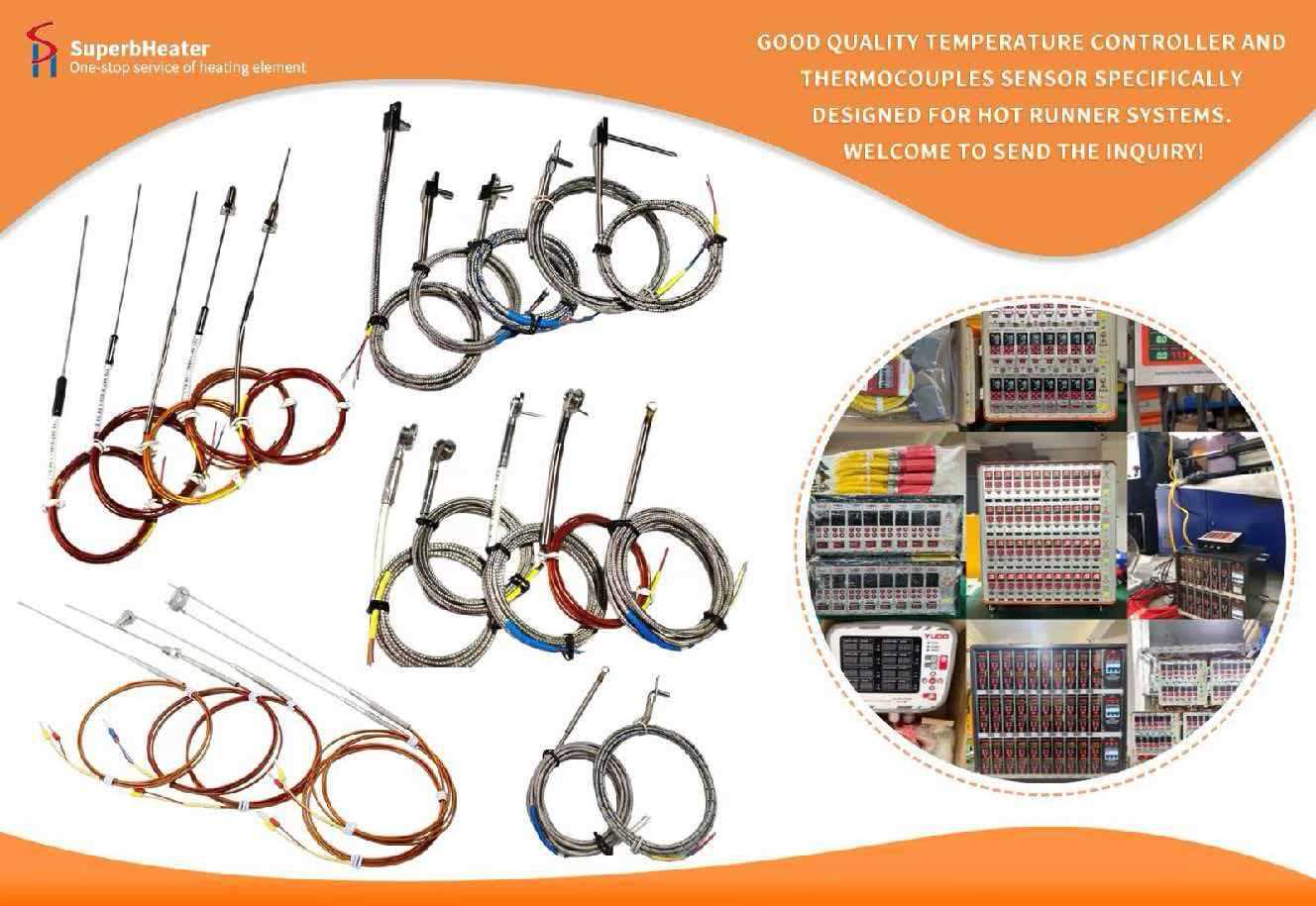
The filling deviations caused by cold runners are completely resolved by high-precision multi-cavity moulds, which utilise a hot runner balanced feeding structure and independent temperature control and flow distribution design.
By utilising the virtual DoE function of mould flow simulation software, it is possible to optimise runner geometry parameters in advance, thereby reducing the number of trial moulding errors and more quickly identifying the optimal filling balance solution.
This system optimisation solution is fully compatible with your current precision injection multi-cavity mould production line. It has the potential to enhance the stability of mass production by substantially reducing defects in multi-cavity products, including dimensional deviations, colour differences, and shrinkage deformation, following its implementation.