I. Optimisation of the Runner System for Root Causes
Control the melt flow resistance deviation within 5% by implementing an H-type or X-type radial symmetrical runner layout that guarantees the length, diameter, and bending angle of the runners from the main runner to each cavity are fully consistent.
To prevent local melt stagnation and degradation, finely polish the inner wall of the runner to Ra0.8 or lower to reduce melt flow friction resistance and inactive zones.
Levelling is accomplished by compensating for the size of the runner in asymmetrical mould configurations. Add flow-blocking steps to the front runner for cavities with an excessively rapid feed; for cavities with an excessively slow feed, widen the runner appropriately. Balance the feed pace of each cavity manually.
II. Improvement of the Hot Runner Temperature Control System
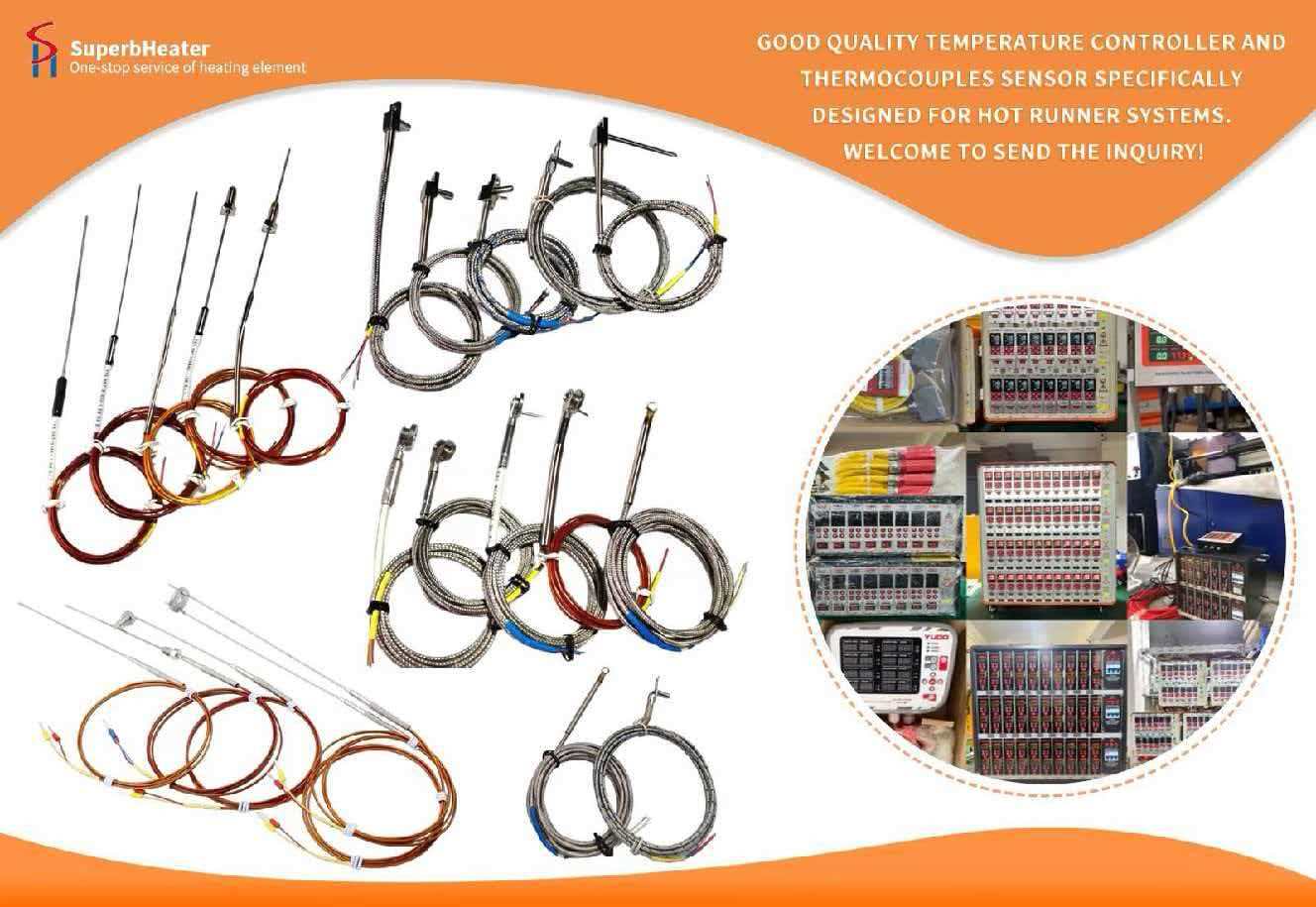
Install an independent PID temperature control module in each hot runner nozzle to ensure that the temperature is controlled accurately within ±0.5℃, with a temperature deviation of ≤3℃ in each zone. This will prevent localised overheating, which can result in uneven melt viscosity.
A hot runner timing control system of the needle valve type is implemented. By precisely regulating the opening and closing times of each gate, the gates in the far cavities open 0.1 to 0.2 seconds in advance, thereby compensating for flow lag and achieving synchronous filling of all cavities.
The hot runner temperature sensor is calibrated on a regular basis to prevent temperature runaway caused by temperature drift, thereby guaranteeing the long-term stability of the production temperature.
III. Optimisation of the Cooling System and Cavity in Balance
The machining accuracy of all cavities is uniformly controlled within ±0.01mm, ensuring that the volume and wall thickness of each cavity are entirely consistent. This eliminates filling deviations that are caused by differences in cavity geometry.
A parallel conformal cooling water circuit is implemented to guarantee that the inlet/outlet water method, distance between the water circuit and the cavity, and diameter of the water circuit are identical for each cavity. The cooling water temperature difference between cavities is ≤1℃, and the cooling speed is fully synchronised.
In order to prevent localised cavity cooling lag and ensure smooth heat dissipation, the water circuit is cleaned routinely to prevent scale buildup. This would necessitate an extension of the overall cooling cycle.
IV. Centralised Management of Venting Systems and Gates
The melt must enter the mould cavities with a uniform instantaneous flow rate, and all gates must be identical in size, location, depth, and width, with a cross-sectional area difference of ≤1% between gates.
The ventilators in each cavity are symmetrically positioned, with a consistent depth and location. They are preferentially located at the end of the melt filling process to prevent confined air in individual cavities from obstructing melt flow, resulting in filling delays and product scorching defects.
V. Implementation of a Digital Operation and Maintenance System
Pressure sensors are installed at each cavity gate to capture real-time pressure-time curves for each cavity. During the filling stage, a curve overlap of ≥95% and a pressure peak difference of ≤3% are required.
A mould maintenance plan that is preventative in nature is implemented. The hot runner nozzles are cleaned of carbonised residue and cavity wear is assessed after every 5000 mould cycles to prevent the degradation of filling consistency as a result of mould ageing.
A formula library is used to store verified and mature process parameters for one-click recall during product and material changes. This process requires only ±5% fine-tuning to rapidly restore stable production.
Currently, you are operating a precision hot runner multi-cavity mould injection production line that is perfectly adapted to this system optimisation solution. The multi-cavity filling time difference can be controlled to within 0.1s after implementation, and the product weight variation coefficient CV can be reduced to ≤ 1.3%. Additionally, the mass production yield can be maintained at over 98%, and the overall production efficiency can be enhanced by 30%.