I. Hardware Optimization
Upgrade to High Power Density Heating Elements: Replace with high power density heating components such as cast aluminum heating plates and ceramic heating coils. Within the limits of the hot runner structure, this increases the heating power per unit area by 20%~30%, significantly accelerating heat transfer.
Optimize Hot Runner Structure Thermal Conductivity: Fill the contact surface between the heating element and the runner plate with high thermal conductivity thermal grease specifically designed for hot runners, eliminating air gap thermal resistance and improving heat transfer efficiency by over 30%.
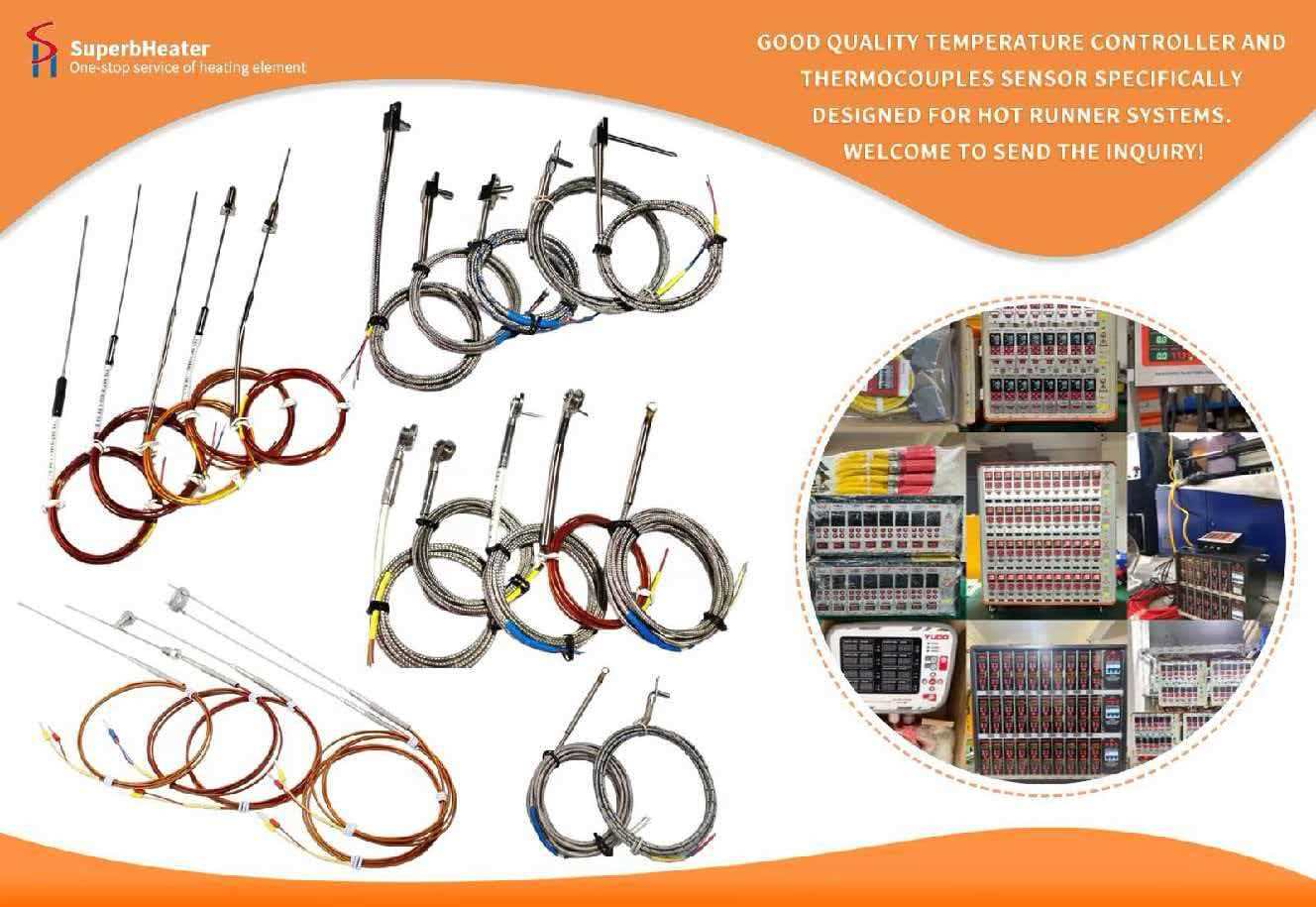
Replace with High-Precision Response Sensors: Replace traditional K-type thermocouples with high-speed temperature sensors with a response time ≤2 seconds, reducing temperature acquisition lag and preventing the temperature control system from delaying heating and slowing down the heating process.
II. Optimized Heating Strategy
Segmented Variable Power Heating Mode: During the low-temperature preheating stage, the heating elements are allowed to operate at 100% full power to quickly raise the hot runner from room temperature to 100°C. After reaching 100°C, the power is limited to below 70%, balancing heating speed and temperature stability.
Elimination of Redundant Holding Time: Provided the hot runner is free of moisture and the insulation resistance is fully qualified, the holding time for the low-temperature section is reduced from 30 minutes to 15 minutes, and the holding time for the medium-temperature section is reduced from 20 minutes to 10 minutes, shortening the total heating time by approximately 30%.
Synchronous Coordinated Heating in Zones: For large multi-cavity hot runners, staggered heating restrictions are eliminated. Provided the total power supply capacity allows, all heating zones start heating simultaneously, avoiding zone waiting that slows down the overall progress.
III. Optimized Pre-process Preparation
Pre-stored Standby Temperature: During non-production intervals, maintain the hot runner at a low standby temperature of 80-100℃. Upon next startup, there's no need to start from room temperature; it can start directly from the mid-temperature range, directly reducing heating time by over 50%.
Pre-calibration: Complete thermocouple calibration and PID parameter self-tuning in advance. Before heating, confirm all hardware connections are normal to avoid wasting time troubleshooting due to abnormal parameters during heating.
IV. Boundary Risk Management
For easily degradable sensitive materials (PVC/POM, etc.), solutions that drastically shorten heating time are not suitable. Maintain the original gradient heating rhythm to avoid localized rapid overheating that could lead to material degradation.
Monitor temperature deviation in each channel throughout the heating process: Ensure the overall temperature difference is ≤ ±5℃ to prevent excessively rapid heating that could cause thermal deformation of hot runner metal components, leading to nozzle misalignment, sealing leaks, and other problems.