I. Optimisation of Runner System Resistance Reduction
Optimise the cross-sectional dimensions of the runners as necessary. To reduce melt flow resistance and accelerate the overall filling speed, moderately increase the runner diameter without affecting melt residence time.
Eliminate frictional resistance and inactive zones by finely polishing the inner walls of the runners to a level below Ra0.8. This will reduce energy loss during melt flow.
To prevent flow stagnation and local pressure loss caused by right-angle corners, ensure seamless melt flow by utilising rounded transitions for all runner corners.
II. Hot Runner Temperature Control Efficiency Improvement Optimise
To reduce melt viscosity and substantially enhance melt flow speed, increase the overall temperature of each zone of the hot runner by 5-10℃ within the upper limit of the material's allowable temperature range.
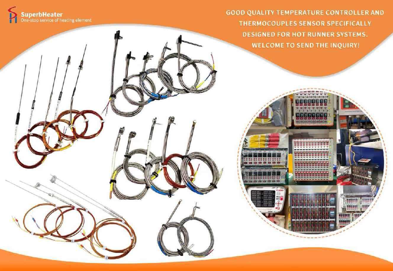
To prevent the obstruction of melt flow and the slowing of the overall filling cadence, it is crucial to maintain the temperature control accuracy of each zone at ±0.5℃.
Utilise a needle valve-type hot runner timing control to ensure that all gates are opened simultaneously, thereby preventing the filling waiting time that is caused by timing mismatches.
III. Enhancement and Acceleration of Injection Moulding Process Parameters
Multi-segment layered injection speed control is implemented during the loading phase. The filling time is considerably reduced by increasing the injection speed of the main filling section of the cavity to 80-120 mm/s, without causing air entrapment or scorching defects.
A sufficient reserve injection pressure is maintained. In order to guarantee that the melt has the necessary force to rapidly fill the cavity, the pressure during the filling stage is maintained at 70%-80% of the equipment's maximum value.
The holding pressure switching point is precisely locked, and the pressure is immediately switched to holding pressure after all cavities have completed 95% filling simultaneously. This prevents unnecessary pressure waiting time during the filling stage.
IV. Mould Auxiliary Structure Optimisation
Each cavity's ventilation system is optimised. The venting grooves are uniformly and symmetrically positioned to prevent back pressure caused by trapped air inside the cavity during filling, which would impede the rapid advancement of the melt.
The temperature of the mould is moderately elevated. The flow resistance of the liquid in the cavity is reduced, and the filling speed is accelerated, by increasing the mould temperature by 5-10℃ for high-viscosity materials.
Guide ribs are incorporated into intricate cavities to facilitate the rapid spread of the liquid, minimise turbulence and stagnation, and enhance the filling efficiency.
V. Optimisation of Multi-Cavity Synchronisation
The speed-up solution is verified by Moldflow mould flow simulation to ensure that the filling time difference between each cavity remains within 0.1 seconds after the speed-up, thereby preventing inconsistent filling in local cavities.
Pressure sensors in each cavity monitor the filling status in real time, guaranteeing that the pressure curve overlap of each cavity is ≥95% following the speed-up and that the filling speed is synchronised without deviation.
Our optimisation solution is entirely compatible with your current precision hot runner multi-cavity mould injection moulding production line. It has the potential to decrease the overall filling time by 20% to 30% after implementation, while also assuring filling consistency. This will further compress the moulding cycle and enhance production efficiency.