I. Optimisation of the Runner System for Root Cause Balancing
Control the melt flow resistance deviation within 5% by implementing an H-type or X-type radial symmetrical runner layout that guarantees the length, diameter, and bending angle of the runners from the main runner to each cavity are fully consistent.
To eliminate dead zones and reduce differences in melt flow friction resistance, finely polish the inner wall of the runner to Ra 0.8 or lower and round all corners.
Levelling is accomplished by compensating for the size of the runner in moulds with an asymmetrical layout. For cavities with an excessively rapid feed, it is recommended to incorporate flow-blocking steps at the front end. Conversely, for cavities with a slow feed, the runner should be widened to mitigate resistance. Balance the feed pace of each cavity manually.
II. Accurate Temperature Regulation of Hot Runners
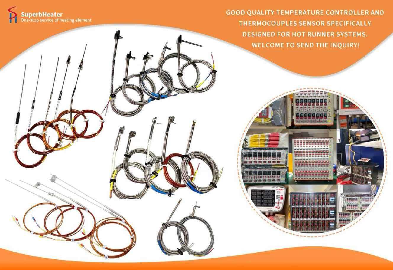
The temperature accuracy of each hot runner nozzle is maintained within ±0.5℃ by an independent PID temperature control module, with a temperature deviation of ≤3℃ in each zone. This prevents localised overheating, which results in uneven melt viscosity.
A hot runner timing control system of the needle valve type is implemented, with the gates in the distal cavities opening 0.1-0.2 seconds in advance to account for flow lag and ensure synchronous injection into all cavities.
In order to guarantee long-term production temperature stability and eradicate temperature drift, the hot runner temperature sensor is calibrated on a regular basis.
III. Centralised Management of Venting Systems and Gates
A uniform instantaneous melt flow rate is guarantyd by the complete consistency of the size, position, depth, and width of all cavity injection gates, with a cross-sectional area difference of ≤1%.
Ventilators are symmetrically positioned in each cavity, with a uniform venting depth and location. They are preferentially located at the end of melt filling to prevent trapped air in individual cavities from obstructing melt flow, resulting in filling lag and product scorching defects.
IV. Collaborative Optimisation of Injection Moulding Process Parameters
During the plasticising stage, a stable screw speed and a moderate back pressure of 3-8 bar assure a completely consistent melt density and viscosity for each injection. Additionally, a unified barrel temperature is maintained.
Multi-stage, layered injection speed control is implemented throughout the entire injection procedure. In the initial stage, the melt is delivered at a low speed and is delivered smoothly. During the intermediate stage, it fills the cavity at a uniform speed. Finally, the injection speed is reduced to ensure a unified seal, ensuring that all cavities are filled synchronously.
A unified pressure holding switch is implemented to prevent premature overflow in certain cavities and underfilling in others once all cavities have been filled to a 95% capacity.
V. Guarantee for Digital Operation and Maintenance and Cooling
A parallel conformal cooling water system is employed, with a cooling water temperature difference of ≤1℃ between cavities. Filling discrepancies are prevented by the complete synchronisation of cooling rates, which prevents mould temperature differences from causing them.
The pressure-time contours of each cavity are collected in real time by installing an in-mold pressure sensor at the gate of each cavity. The peak pressure difference during the filling stage must be ≤3%, and the curve overlap must be ≥95%.
To prevent mould ageing from compromising filling uniformity, the hot runner nozzles are cleansed for carbonised residue and cavity wear is checked every 5000 batches.