Replacing a thermocouple during production is a high‑risk activity that, if done incorrectly, can lead to extended downtime, scrap, or even mold damage. A well‑planned procedure minimizes the impact. The first step is to prepare the replacement sensor. Unpack the new thermocouple and perform a quick check: measure the resistance (should be low, e.g., <5 ohms) and insulation resistance (>100 MΩ). Verify that the connector type and cable length match the old one. If the controller requires a specific offset for the zone, note the existing offset value. The second step is to schedule the replacement during a planned stop, such as a shift change or a material change, to minimize production loss. If no planned stop is available, wait for a natural break, such as a hopper refill. The third step is to identify the exact zone and confirm its location on the mold. Use the wiring diagram and physically trace the cable to ensure no confusion. The fourth step is to isolate the zone: turn off the heater for that zone using the controller. Do not turn off the entire system, as the neighboring zones will still be hot, which will help the zone stay warm. Wait for the zone temperature to drop to below 120°C-this is important because the metal expands and may seize the thermocouple. Cooling too fast can cause thermal shock, so use the controller's "cool down" function if available. The fifth step is to carefully remove the old thermocouple. Use a wrench on the hex flats (if any), not on the probe body, to avoid bending. If it is stuck, apply a penetrating oil and gently work it loose. Do not force it; if necessary, use a small propane torch to heat the mold block slightly (but avoid overheating the resin). Once removed, clean the mounting hole thoroughly with a drill bit of the correct size and a solvent (e.g., acetone) to remove carbonized resin and anti‑seize residue. The sixth step is to apply a small amount of high‑temperature anti‑seize to the threads of the new thermocouple (but not on the tip). Insert the new probe, ensuring it bottoms out or reaches the correct depth. Tighten it to the recommended torque (typically 3–5 N·m for M6). Connect the cable to the controller, observing correct polarity. The seventh step is to restart the zone. Increase the setpoint to standby temperature (e.g., 150°C) at a controlled rate (use a ramp function of about 5°C/min). Once stable, increase to the full operating setpoint. The eighth step is to monitor the zone's performance for the first 10 cycles. Ensure the temperature stabilizes without excessive overshoot and that the part quality is consistent. If the zone is on a multi‑cavity mold, compare the part weight from this cavity with the others to verify proper function. By following this procedure, replacements can be completed in 30–60 minutes with minimal production loss and no risk of mold damage. Having a pre‑prepared kit with the correct replacement sensor and tools ready in advance is key to a smooth operation.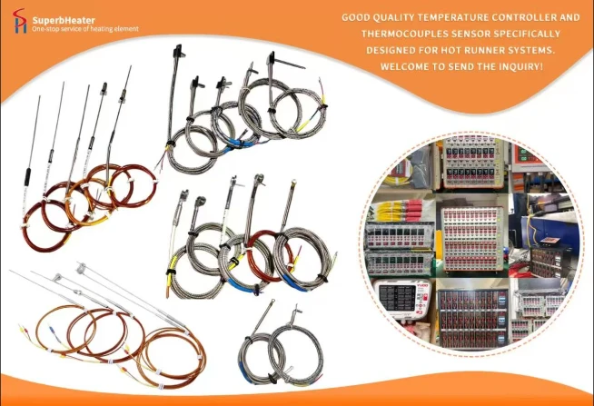

 English
- English
- Français
- Deutsch
- 日本語
- Italiano
- Español
- Português
- русский
- Indonesia
- عربي
- Ελληνικά
- Polski
- فارسی
- עברית
- Kreyòl Ayisyen
- 한국어
- Türkçe
- slovenčina
- Bai Miaowen
- Cymraeg
- dansk
- Lietuvių
- Malti
- Svenska
- Srbija jezik (latinica)
- O'zbek
- ไทย
- suomi
- magyar
- Eesti
- Català
- slovenščina
- Melayu
- Български
- اردو
- România limbi
- bosanski
- हिंदी
- Gaeilgenah Éireann
- Việt Nam
- বাংলা
- íslenska
- Norsk
- Latviešu
- hrvatski
- Nederlands
- Čeština
- українська


