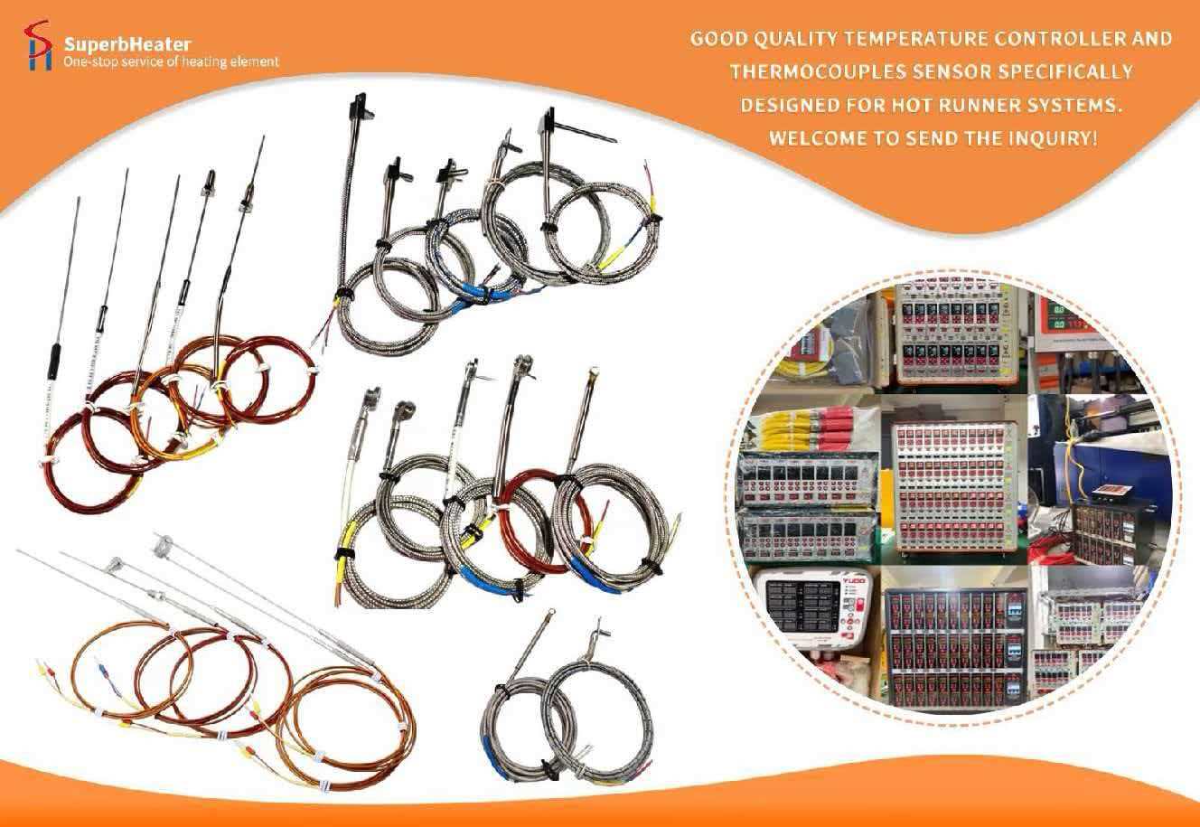
Preparation before Calibration: Prepare a Class II standard platinum-rhodium/platinum thermocouple, a low-potential DC potentiometer with a 0.02-degree precision, and a dry-block furnace/constant temperature bath. Ensure that all standard equipment is within its calibration validity period.
Pre-heat the Husky thermostat and hot runner system for 30 minutes. Check that the thermocouple wire is secure, the temperature field is stable, and there are no underlying hardware flaws like weak connections or short circuits.
Thermocouple Body Characteristic Calibration: Connect the hot junctions of the Husky thermocouple to be calibrated and the standard thermocouple and set them in the constant temperature bath/calibration furnace, making sure that their measuring ends are in the same temperature field.
Set up 3-5 calibration points to cover common temperature ranges for hot runner systems (e.g., 100℃, 300℃, 500℃, 800℃ for K-type thermocouples). Hold each temperature point at the same temperature for 15-20 minutes until stable. After stabilisation, take readings in a forward and backward order of standard-catheter-standard, at least four times.
Calculate the actual temperature and the difference between the two using the appropriate national standard thermoelectric potential-temperature conversion table; this is the thermocouple body error. If the deviation is stable and fixed, record it for future correction in the temperature controller.
Full-Link Calibration
Calibrate the compensation lead by connecting both ends to the standard thermocouple and the standard temperature measurement instrument. Put the heated end in a 100℃ boiling water bath and the cold end in a 0℃ freezing point apparatus. Measure the circuit thermoelectric potential and compare it to the theoretical thermoelectric potential in the standard calibration table to ensure the discrepancy is not more than ±5μV. Verify the polarity at the same time: red is positive, and the opposite colour is negative, to avoid reversing the connection, which might double the temperature measurement variance.
To calibrate the cold junction compensator, place it in a constant temperature chamber and set three common room temperature points: 20℃, 25℃, and 30℃. Connect the cold end of the compensator to the freezing point apparatus (0℃) and measure the compensated thermoelectric potential output. Compare this to the theoretical compensated potential to ensure that the compensation deviation does not exceed ±0.1℃.
Temperature Controller Parameter Setup
To create a full-temperature-range linear compensation curve, navigate to the Husky temperature controller's "Advanced Calibration" menu and select the multi-point linear compensation parameter setting interface. Enter the error correction values for each temperature point sequentially.
To minimise extra system errors caused by cold junction temperature drift, ensure that the cold junction compensation settings are exactly matching the recorded ambient temperature at the wiring point.
Start the temperature controller's PID self-tuning program to let the system adjust to the new linear compensation features and optimise the temperature control curve.
Verification of the closed-loop system after calibration
Run at a steady temperature for two hours. Randomly select various temperature points from the whole temperature range for comparison testing with ordinary thermocouples. Check that the temperature measurement deviation is ≤±1℃, the temperature fluctuation is ≤±1℃, and there is no drift or leap. Calibration has completed.
This calibration procedure fully meets industrial metrology calibration standards and can entirely eradicate the Husky thermocouple system error, ensuring long-term stability of hot runner temperature measurement accuracy.