The interaction between a thermocouple and its temperature controller is more complex than a simple voltage reading. The controller must perform several signal‑conditioning steps to convert the raw microvolt signal into an accurate temperature value and then use that value for PID control. First, the controller measures the thermocouple's output voltage using a high‑precision analog‑to‑digital converter (ADC). Because the thermocouple's reference junction (the cold end at the controller terminals) is not at 0°C, the controller must compensate for this using a built‑in cold junction compensation (CJC) sensor-typically a thermistor or solid‑state sensor placed adjacent to the input terminals. The CJC measures the ambient temperature and adds the appropriate offset voltage to the thermocouple signal. If the CJC is inaccurate or poorly placed, the entire reading shifts. After digitisation, the controller applies linearisation using polynomial equations or lookup tables that conform to the thermocouple type (J, K, etc.) according to ITS‑90 standards. The result is a temperature value that is displayed and used for control. The PID algorithm then compares this value with the setpoint and calculates an output power percentage, which is sent to the heater's solid‑state relay or phase‑angle controller. Modern controllers also incorporate advanced features such as autotuning, which automatically determines optimal PID parameters by analysing the zone's thermal response. Some controllers can detect thermocouple open circuits, short circuits, and reversed polarity, and issue alarms. More advanced models monitor the rate of change of the temperature to detect a sluggish sensor or a heater failing. Communication between the controller and the thermocouple is entirely analogue (voltage), but modern controllers often use digital interfaces (such as RS‑485, Modbus, Profibus, or EtherNet/IP) to communicate with a plant‑wide supervisory system. This allows remote monitoring, data logging, and recipe management. Understanding this communication chain is crucial for troubleshooting-if the controller displays a wrong temperature, the error could be in the thermocouple, the CJC, the linearisation table, or the ADC. Some controllers also offer sensor offset adjustments to compensate for known deviations. For critical applications, some systems use two thermocouples per zone-one for control and one for backup or deviation monitoring-with the controller automatically switching if the primary fails. This level of integration makes the thermocouple‑controller pair the true brain of the hot runner, and their compatibility is essential for stable operation.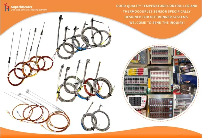

 English
- English
- Français
- Deutsch
- 日本語
- Italiano
- Español
- Português
- русский
- Indonesia
- عربي
- Ελληνικά
- Polski
- فارسی
- עברית
- Kreyòl Ayisyen
- 한국어
- Türkçe
- slovenčina
- Bai Miaowen
- Cymraeg
- dansk
- Lietuvių
- Malti
- Svenska
- Srbija jezik (latinica)
- O'zbek
- ไทย
- suomi
- magyar
- Eesti
- Català
- slovenščina
- Melayu
- Български
- اردو
- România limbi
- bosanski
- हिंदी
- Gaeilgenah Éireann
- Việt Nam
- বাংলা
- íslenska
- Norsk
- Latviešu
- hrvatski
- Nederlands
- Čeština
- українська


