I. Quick Preparation Before Calibration
Power on the hot runner signal generator and allow it to warm up for 30 minutes to allow the internal crystal oscillator and analog circuitry to reach thermal stability.
Complete the system self-test, confirming that all channels have no hardware errors. Disable all modulation functions and select a standard DC/sine wave as the output waveform.
Connect the process calibrator, high-precision frequency counter, multi-channel oscilloscope, and other reference calibration equipment, and allow the reference equipment to warm up.
II. Frequency Reference Recalibration
Set the signal generator output to a typical 10MHz frequency and measure the actual output value using the frequency counter.
If the deviation exceeds ±1ppm, adjust the frequency correction factor until the deviation is zero. Complete the calibration by covering the commonly used 10kHz, 1MHz, and 10MHz frequency bands for hot runner calibration.
III. Output Amplitude Recalibration
Set the commonly used 10mVpp, 100mVpp, and 10Vpp amplitude levels for hot runner calibration point by point, and measure the actual output value using the reference equipment.
If the deviation exceeds ±1%, adjust the gain correction value to eliminate amplitude output error. For high amplitude ranges, use the oscilloscope's high-impedance input mode to avoid load deviation.
IV. Specific Recalibration of Thermal Signals
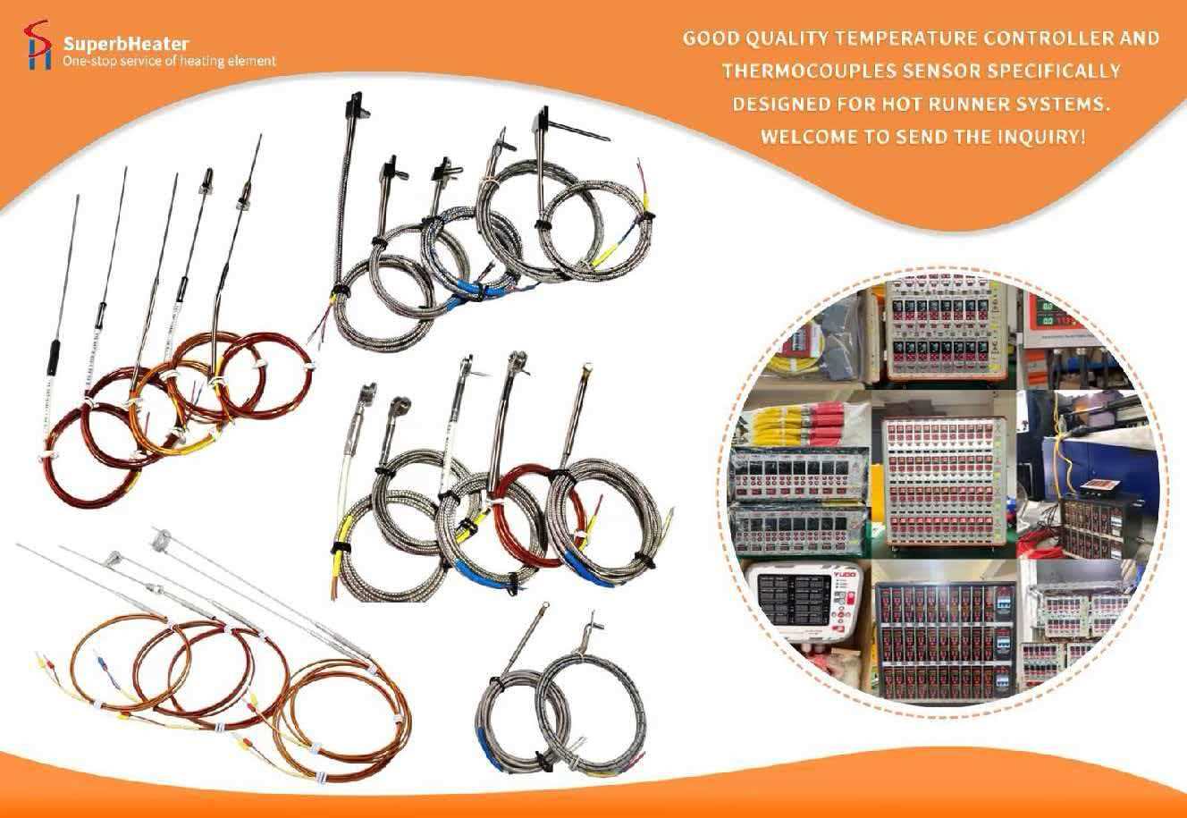
Thermocouple Signal Calibration: Set up millivolt analog signals for commonly used K-type and J-type thermocouples. Using the process calibrator's measurement value as a reference, adjust the thermocouple output correction coefficient.
RDB Signal Calibration: Set up analog resistance signals for commonly used Pt100 and Cu50 RTDs. Using the process calibrator's measurement value as a reference, adjust the RTD output correction coefficient to ensure a deviation ≤ ±0.05%FS.
V. Multi-Channel Synchronous Recalibration
Using the rising edge of the main channel waveform as a reference, use a multi-channel oscilloscope to acquire all slave channel output signals and read the phase time difference of each channel.
Fine-tune the delay correction coefficient channel by channel until the synchronization deviation of all channels is ≤0.01s. In long-distance trigger line scenarios, enable the cable resistance compensation function to offset transmission delay.
VI. Verification and Parameter Consolidation
Randomly select 10 calibration points across the entire range for recalibration to confirm that the accuracy deviation of all points is within the allowable range.
Data was collected continuously for 30 minutes to confirm no instability caused by drift over time.
All calibration correction factors were saved to the device's non-volatile memory, generating a calibration profile to complete the recalibration.
This recalibration process is streamlined and efficient, enabling rapid restoration of device accuracy and meeting the rapid recalibration needs of hot runner production lines.